AutoCAD's built-in EXPLODE and MESHSMOOTH commands can convert solids to mesh, but they give you limited control over the output mesh quality and don't always produce clean polyface mesh objects compatible with downstream export workflows. Automesher Application adds the AmConvertMesh command, which converts 3D solids to polyface mesh with precise FACETRES-based quality control and also supports the reverse direction - polyface mesh back to 3D solid.
This guide shows how to convert 3D solids to polyface mesh in AutoCAD in four steps, including how to set FACETRES for the mesh density you need.
How to Convert 3D Solid to Polyface Mesh: Step-by-Step
📥 Install Automesher Application
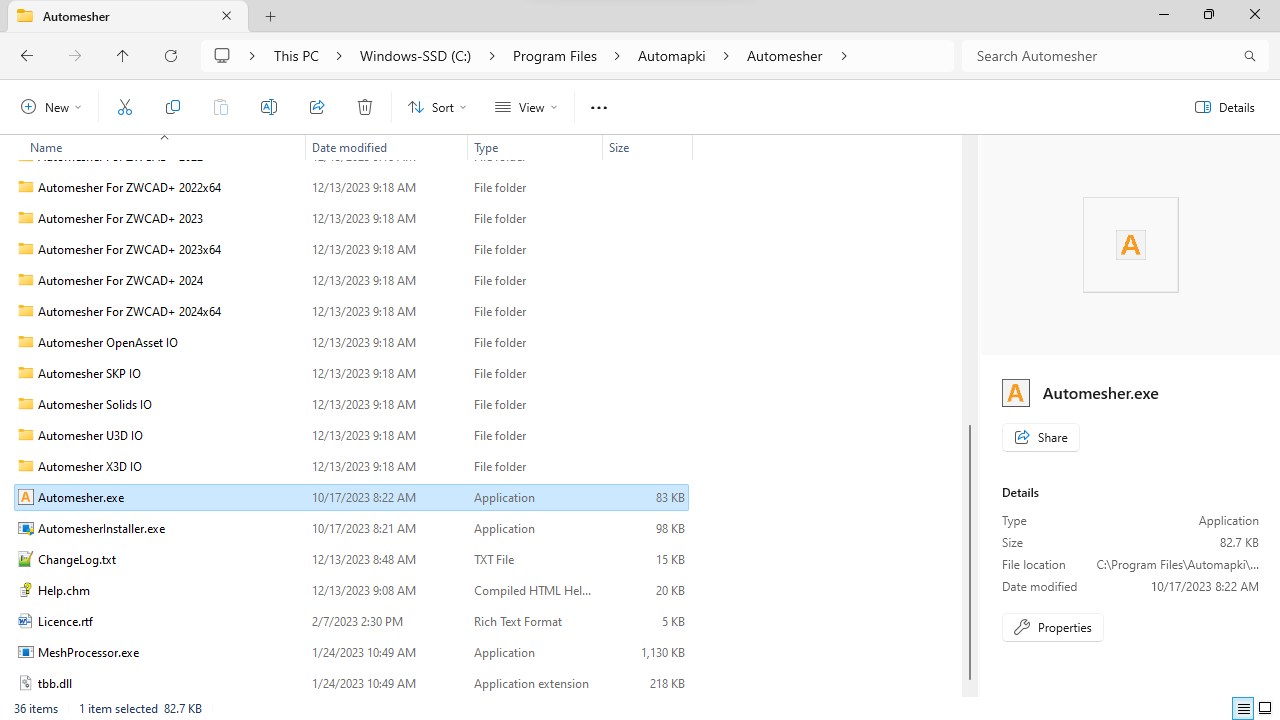
Download and install Automesher Application for AutoCAD. After installation, restart AutoCAD to autoload the plugin. Automesher adds the AmConvertMesh command and a dedicated ribbon tab to your AutoCAD environment. The same plugin also works in BricsCAD, ZWCAD, and GstarCAD.
▶️ Set FACETRES Before Converting
Before running the conversion, set the FACETRES system variable to control how finely the solid's curved surfaces are tessellated into polygon faces. Type FACETRES in the AutoCAD command line and press Enter, then enter a value between 0.01 and 10:
- Low values (0.5–1) - coarser mesh, fewer faces, smaller file size. Use for draft outputs, visualization, or when file size is a priority over surface smoothness.
- Medium values (2–4) - balanced mesh density for most workflows. Curved surfaces look reasonably smooth without producing excessively large files.
- High values (5–10) - fine mesh, more faces on curved surfaces, larger file size. Use for 3D printing where surface smoothness is critical, or for high-quality rendering exports.
The default FACETRES value in AutoCAD is 0.5, which often produces a noticeably coarse mesh on curved solids. Increase it to at least 2–4 for most practical conversion workflows.
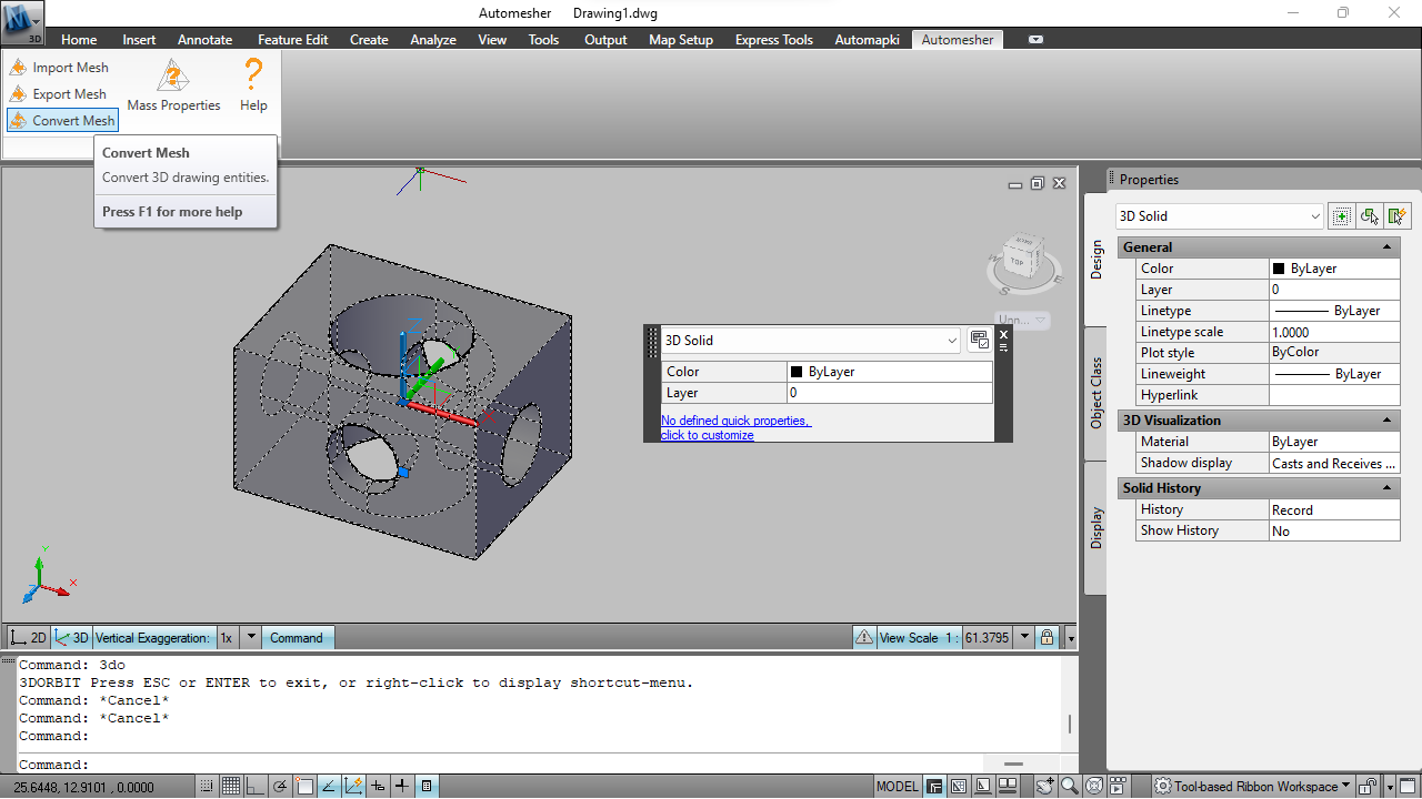
🧊 Run AmConvertMesh and Select Polyface Mesh Output
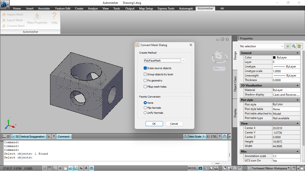
Type AmConvertMesh in the AutoCAD command line and press Enter. Select the 3D solid objects you want to convert and press Enter to confirm the selection. In the Automesher conversion dialog, choose the following settings:
- Convert to PolyfaceMesh - produces standard AutoCAD polyface mesh entities
- Erase Source Entities - removes the original 3D solid after conversion to avoid duplicate geometry occupying the same location
- Group by Layer - assigns the resulting mesh to the same AutoCAD layer as the source solid, preserving drawing organization
Click OK to run the conversion. Automesher tessellates the solid at the current FACETRES quality level and inserts the polyface mesh objects into the drawing.
⏱️ Verify and Export the Polyface Mesh
Use the AutoCAD Properties panel to verify the converted objects are listed as Polyface Mesh type. The mesh is now ready for export using Automesher's AmExportMesh command to STL, OBJ, FBX, STEP, or other formats - or for further editing using AutoCAD's mesh editing tools.
Understanding FACETRES: Mesh Quality vs File Size
FACETRES controls the chord height tolerance for solid tessellation. A lower value allows larger deviations between the mesh face and the true mathematical surface, producing fewer, larger triangles. A higher value tightens the tolerance, producing more faces that more closely approximate smooth curves.
For a sphere of radius 100mm, a FACETRES of 0.5 might produce ~300 faces; FACETRES of 5 produces ~3,000 faces; FACETRES of 10 produces ~12,000 faces. The right value depends on what the mesh will be used for - coarse for context models, fine for print-quality exports.
Frequently Asked Questions
-
Can AutoCAD convert solids to polyface mesh without a plugin?
AutoCAD has limited built-in solid-to-mesh conversion options, but they offer no control over mesh quality and produce different entity types than polyface mesh. The AmConvertMesh command from Automesher gives full control over tessellation quality via FACETRES and produces standard polyface mesh objects compatible with all AutoCAD export workflows.
-
What FACETRES value should I use for 3D printing?
For 3D printing, use FACETRES 4–8 depending on the size and detail level of the model. A value of 5 is a good starting point - it produces smooth curves without generating excessively large STL files that slow down slicers. Check the converted mesh visually in AutoCAD before exporting to STL to confirm curved surfaces look acceptable at print scale.
-
Does converting to polyface mesh change the geometry?
The polyface mesh approximates the original solid's curved surfaces as flat polygon faces - the smaller the FACETRES value (coarser mesh), the more visible the approximation. Flat faces of the original solid are converted exactly without approximation regardless of FACETRES. The conversion is a one-way approximation; reconverting back to solid produces a faceted BREP solid, not the original smooth parametric solid.
-
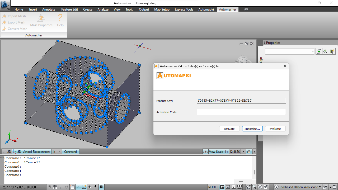
How many conversions does the trial version allow?
The free evaluation version of Automesher Application supports up to 20 conversions. The full licensed version provides unlimited conversions.
Summary
Converting AutoCAD 3D solids to polyface mesh requires setting FACETRES before running AmConvertMesh - the quality of the tessellation is entirely controlled by that variable. Automesher handles the conversion in four steps with full control over output entity type, layer assignment, and source entity removal. The same plugin supports the reverse direction and works identically in AutoCAD, BricsCAD, ZWCAD, and GstarCAD.
👉 Ready to convert? Download Automesher add-on and try it free for up to 20 conversions.