The STL format is ideal for 3D printing, but it stores geometry as a raw triangle mesh - no parametric data, no solid model, no editability. To use an STL file in a professional CAD workflow, you need to convert it to STEP format first.
This guide explains how to convert STL to STEP using Autoconverter or Autoshaper, including how to clean up mesh errors before export to get the cleanest possible STP output for SolidWorks, Fusion 360, AutoCAD, CATIA, Creo, and Inventor.
Why Convert STL to STEP?
STL files contain only triangle mesh data - there is no concept of solid bodies, parametric features, or design intent. This makes them unsuitable for direct use in CAD engineering workflows. STEP solves this in several ways.
STEP uses faceted BREP (Boundary Representation) entities, which CAD software can import as solid or surface bodies and edit directly. It is an ISO-standardized format accepted by every major CAD platform, eliminating the compatibility issues that come with proprietary mesh formats. STEP also preserves assembly structure, colors, and user attributes - none of which are supported by STL. And because STEP is the standard interchange format for manufacturing, converting your STL to STEP is often a hard requirement before sending a model to a CNC machinist, injection mold designer, or engineering contractor.
How to Convert STL to STEP: Step-by-Step
📥 Download and Install Autoconverter or Autoshaper
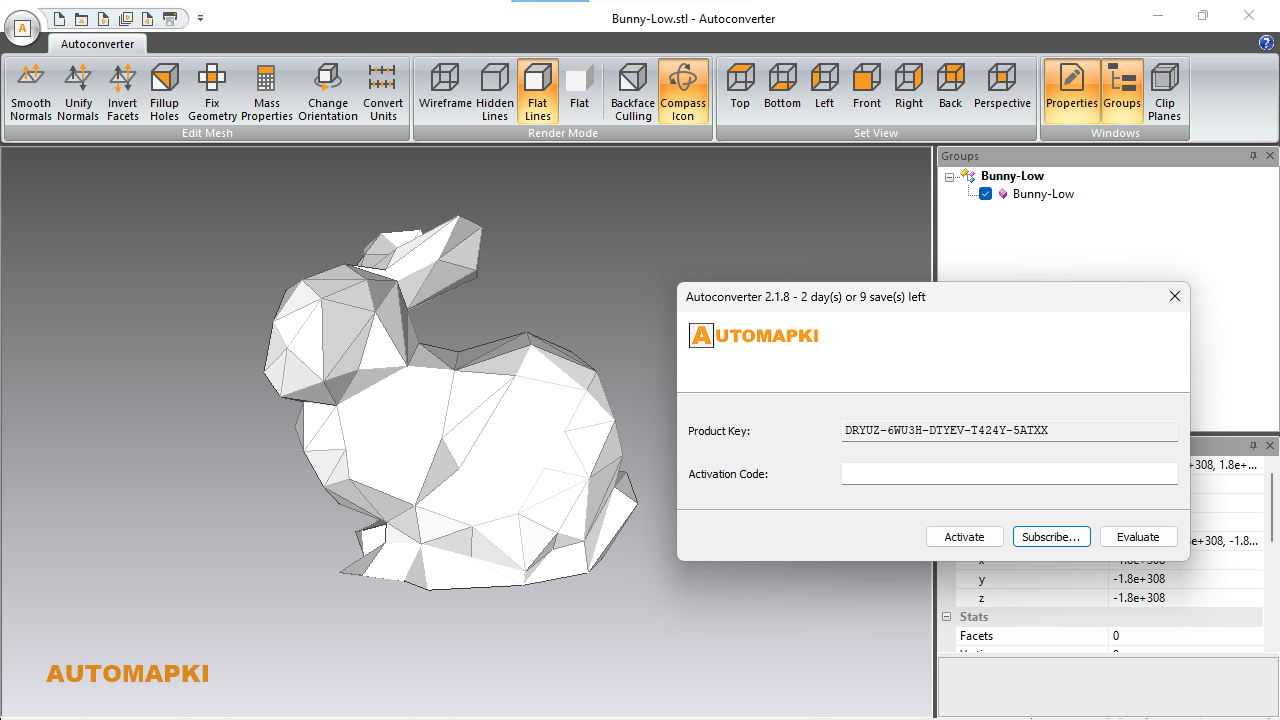
Download Autoconverter or Autoshaper and install on Windows. Both applications support STL import and STEP export natively. Launch the application from the Windows Start menu.
📂 Import Your STL File
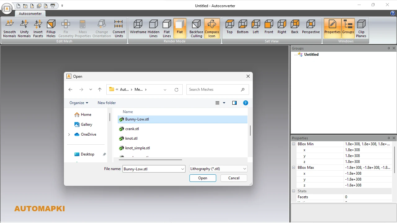
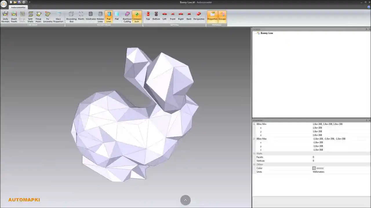
Click Open… from the file menu and select your .stl file, or drag and drop it into the application window. The mesh loads into the 3D viewport so you can inspect it before converting. Both ASCII and binary STL formats are supported.
🔧 Fix Mesh Errors Before Export
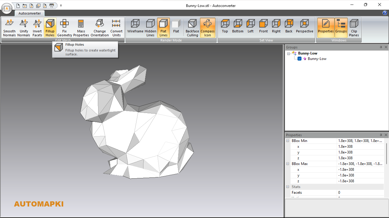
STL files from 3D scanners, online repositories, or 3D printing slicers frequently contain mesh errors that cause problems in STEP output. Before exporting, run the built-in mesh repair tools:
- Fix Geometry: Detects and repairs degenerate triangles, flipped normals, and non-manifold edges that would cause invalid BREP entities in the STEP file.
- Fillup Holes: Closes gaps in the mesh surface to make it watertight - a requirement for generating a valid solid body in STEP format.
Skipping this step is the most common reason an STL-to-STEP conversion produces geometry that SolidWorks or Fusion 360 cannot import cleanly.
🔄 Export to STEP Format
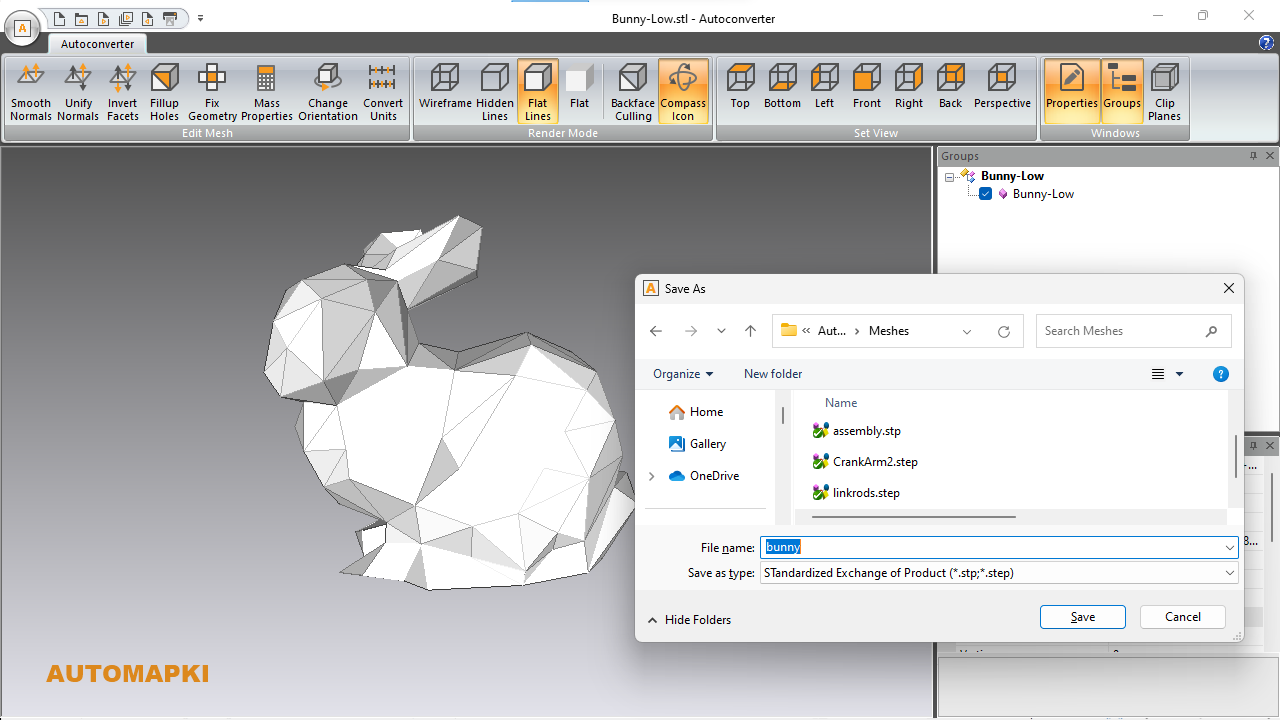
Click Save As… and select STEP as the output format. The converter writes the mesh as faceted BREP entities in the STEP file - a representation that all major CAD systems can read as an importable solid or surface body. Both .stp and .step file extensions are supported.
⏱️ Open in Your CAD Application
Import the output STEP file into SolidWorks, Fusion 360, AutoCAD, CATIA, Creo, or Inventor. The geometry loads as an editable solid body ready for parametric design, measurement, simulation, or manufacturing preparation.
Common STL to STEP Use Cases
- 3D scan to CAD - converting scanned STL meshes into editable STEP models for reverse engineering
- 3D print model to engineering drawing - taking a print-ready STL and preparing it for dimensioning and tolerancing in SolidWorks or Inventor
- Supplier file exchange - manufacturers require STEP format; STL is not accepted in most CNC or injection molding workflows
- Cross-software collaboration - sharing models between teams using different CAD platforms where STL import is limited to mesh-only bodies
- FEA and simulation - simulation tools require solid geometry; STL mesh bodies are often unsuitable for meshing in FEA preprocessors
Frequently Asked Questions
-
Can I convert STL to STEP without SolidWorks or Fusion 360?
Yes. Autoconverter and Autoshaper convert STL to STEP as standalone Windows applications - no CAD software installation required on the conversion machine.
-
Will the STEP file be editable after conversion from STL?
The STEP output uses faceted BREP representation, which CAD software imports as a solid or surface body. Direct feature editing (like modifying a fillet or boss) is not possible since STL has no parametric data - but you can use the imported body as the basis for new parametric features in SolidWorks, Fusion 360, or Inventor.
-
Why does my STEP file fail to import in SolidWorks after conversion?
The most common cause is an unrepaired STL mesh - holes, non-manifold edges, or flipped normals prevent the converter from generating a valid closed solid. Run the Fix Geometry and Fill Holes tools in Step 3 before exporting, then retry the conversion.
-
How many STL files can I convert for free?
The free evaluation version of Autoconverter supports up to 10 file conversions. The full licensed version provides unlimited conversions and adds batch processing for converting entire folders of STL files at once.
Summary
Converting STL to STEP bridges the gap between mesh-based 3D printing workflows and parametric CAD engineering. Autoconverter handles the full conversion pipeline - mesh import, geometry repair, and STEP export - in a few steps, producing output that opens cleanly in SolidWorks, Fusion 360, CATIA, Creo, AutoCAD, and Inventor.
👉 Ready to convert? Download Autoconverter and try it free for up to 10 conversions - or explore Autoshaper for NURBS-based solid modeling output from STL input.