STEP files (.step, .stp) store geometry as precise NURBS surfaces and solid bodies - ideal for engineering and CAD workflows, but not directly usable by 3D printers or mesh-based tools. STL is the universal format for 3D printing: every slicer, printer, and additive manufacturing service accepts it. Converting STEP to STL bridges that gap.
This guide shows how to convert STEP to STL in five steps using Autoconverter, including how to control tessellation quality to get the right balance between mesh detail and file size for your specific printing or modeling use case. No CAD software required.
Why STEP Files Need to Be Converted to STL for 3D Printing
STEP is an ISO-standardized engineering format that represents geometry mathematically - curves and surfaces are stored as exact equations, not as triangles. This makes STEP excellent for precision CAD work, but 3D printers and slicers (Cura, PrusaSlicer, Bambu Studio, Chitubox) can only process triangle meshes, which is what STL provides.
Converting STEP to STL is called tessellation - the process of approximating smooth NURBS surfaces as a mesh of flat triangular faces. The quality of that tessellation determines how smooth curved surfaces look in the final print, and how large the output STL file is. Getting this balance right is the key step in the conversion.
How to Convert STEP to STL: Step-by-Step
-
📥 Download and Install Autoconverter
Download Autoconverter and install it on Windows. It reads STEP files natively using the Open Cascade technology stack - the same geometric kernel used by professional CAD tools - ensuring accurate tessellation of complex NURBS geometry. No SolidWorks, Fusion 360, or other CAD installation is required.
-
🚀 Launch Autoconverter
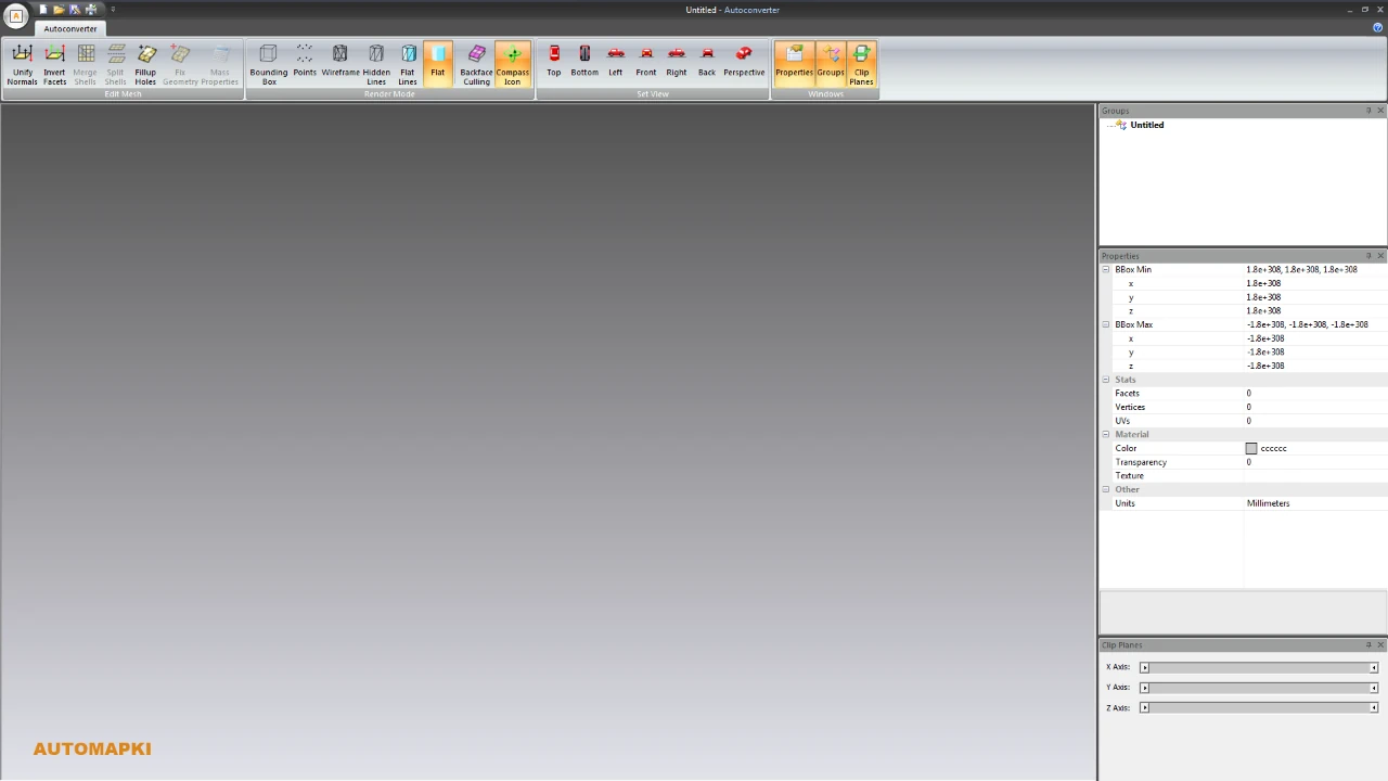
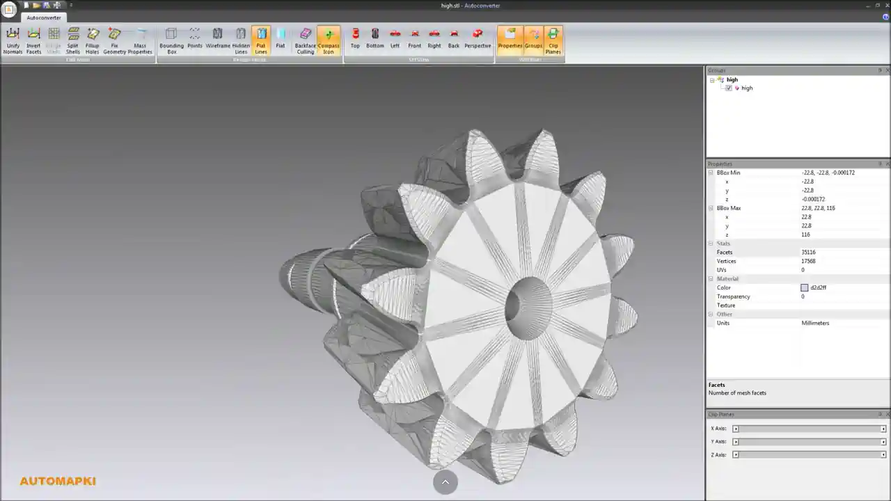
Open Autoconverter from the Windows Start menu. The interface includes a 3D viewport for previewing models before conversion, a ribbon bar, and a properties panel for inspecting geometry data.
-
📂 Open Your STEP File
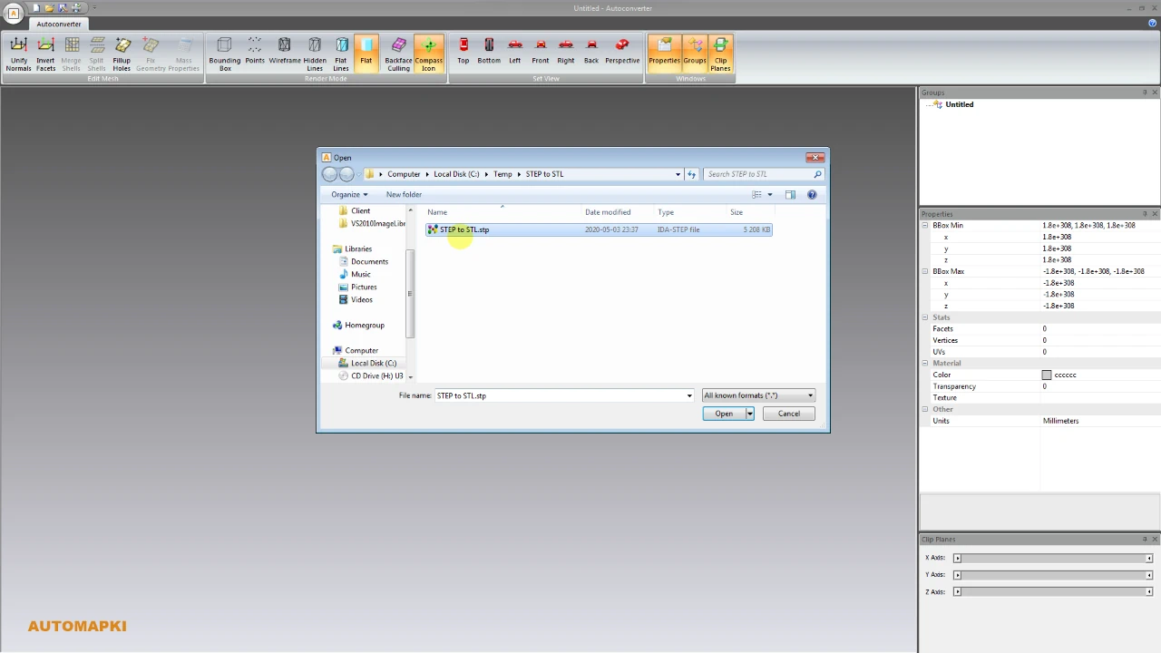
Click Open… and select your .step or .stp file, or drag and drop it into the application window. The model loads into the 3D viewport - inspect it before converting to confirm all geometry loaded correctly. Both AP203 and AP214 STEP versions are supported, covering the full range of files produced by SolidWorks, CATIA, Creo, NX, Inventor, FreeCAD, and other CAD tools.
-
📐 Adjust Tessellation Quality
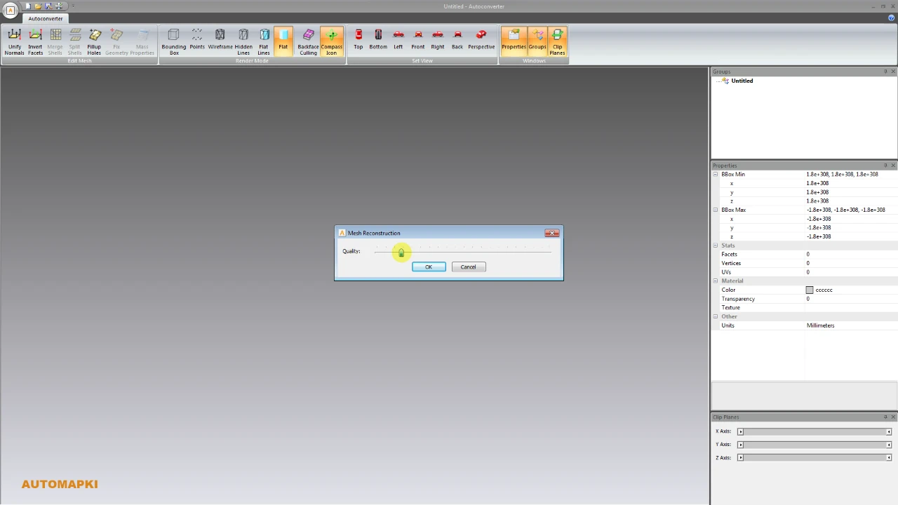
This is the most important step in STEP-to-STL conversion. Before exporting, set the tessellation quality to control how finely the NURBS surfaces are approximated as triangles:
- High quality - more triangles, smoother curves, larger STL file. Use for visible surfaces in final prints, detailed models, or when printing on high-resolution resin printers.
- Medium quality - balanced mesh density for most engineering and product design prints. The practical default for most workflows.
- Low quality - fewer triangles, lighter file, faster slicer processing. Use for draft prints, prototypes, or large assemblies where file size matters more than surface smoothness.
A quick way to check: after setting quality, look at the curved surfaces in the viewport. If arcs appear faceted at your expected print resolution, increase the tessellation setting. Once satisfied, proceed to export.
-
📤 Export to STL Format
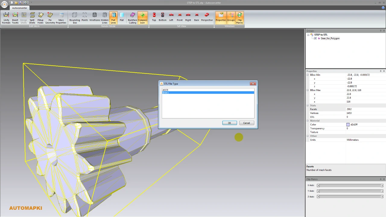
Click Save As… and select STL as the output format. Autoconverter offers two STL encoding options:
- Binary STL - compact file format, typically 5–10x smaller than ASCII. Accepted by all modern slicers and printers. Use this by default.
- ASCII STL - human-readable text format. Use only if a downstream tool specifically requires it - ASCII files are significantly larger and slower to process.
Choose your output filename and destination, click Save, and the STL is ready for import into your slicer or manufacturing workflow.
STEP vs STL: Key Differences
| Feature | STEP (.step, .stp) | STL (.stl) |
|---|---|---|
| Geometry type | NURBS surfaces and solid bodies | Triangle mesh only |
| Curve accuracy | Mathematically exact | Approximated by tessellation |
| File size | Compact (mathematical representation) | Larger (stores all triangle coordinates) |
| Colors | ✅ Yes (assembly level) | Limited (binary STL extensions only) |
| Assembly structure | ✅ Yes | ❌ No |
| 3D printing | ❌ Not directly supported | ✅ Universal slicer format |
| CAD editing | ✅ Parametric solid editing | ❌ Mesh editing only |
| ISO standard | ✅ Yes | ❌ No (de facto standard) |
Tips for Better STEP to STL Results
- Start with medium tessellation and adjust - high quality produces very large STL files for complex assemblies; only increase if curved surfaces look too faceted at your print resolution.
- Use binary STL by default - unless your target tool specifically requires ASCII, binary is always the better choice for file size and processing speed.
- Check the model in your slicer before printing - import the STL into Cura, PrusaSlicer, or Bambu Studio and inspect it at print scale. Issues visible at normal zoom in the converter may not be visible at print scale.
- For large assemblies, export parts separately - converting a complex multi-part STEP assembly to a single STL can produce very large files. Consider exporting individual components as separate STL files for better slicer control.
Frequently Asked Questions
-
Do I need SolidWorks or another CAD tool to convert STEP to STL?
No. Autoconverter reads STEP files natively and does not require any CAD software installed on the conversion machine. It works as a standalone Windows application.
-
Which STEP versions does Autoconverter support?
Autoconverter supports all major STEP standards - AP203, AP214, and AP242 - covering files from essentially every professional CAD application: SolidWorks, CATIA, Creo, NX, Inventor, FreeCAD, and more.
-
Why does my converted STL look faceted on curved surfaces?
This is caused by low tessellation quality in Step 4. Increase the tessellation setting and reconvert - higher quality produces more triangles that better approximate the original NURBS curves. The trade-off is a larger STL file.
-
Can I also convert STL back to STEP?
Yes. Autoconverter supports both directions. See the STL to STEP conversion guide for details on converting mesh geometry back to a STEP solid format.
-
Is there a free trial?
Yes. The free evaluation version of Autoconverter supports up to 10 file conversions. The full licensed version provides unlimited conversions and batch processing.
Summary
Converting STEP to STL is the standard path from precision CAD engineering geometry to 3D printing. The key variable is tessellation quality - higher quality produces smoother prints at the cost of larger STL files. Autoconverter handles the conversion in five steps using Open Cascade's industry-grade geometric kernel, with no CAD software required and support for all major STEP versions.
👉 Ready to convert? Download Autoconverter and try it free for up to 10 conversions.