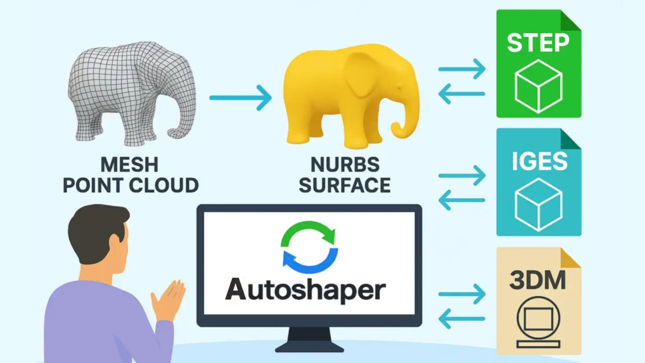
3D scanners and photogrammetry pipelines produce point clouds and triangle meshes - dense, unstructured data that carries accurate shape information but cannot be directly edited in parametric CAD software. You cannot run a Boolean subtract on an STL file in SolidWorks. You cannot assign a draft angle to a polygon face in CATIA. You cannot generate a toolpath from a raw point cloud in a CAM system. To unlock those workflows, the geometry needs to be reconstructed as NURBS surfaces: smooth, mathematically defined patches that CAD tools treat as native, editable geometry.
Autoshaper performs this reconstruction automatically. It reads point cloud files (XYZ/ASC, PLY) and triangle mesh files (STL, OBJ, SKP, 3DM), fits NURBS patches to the surface geometry, and exports the result to STEP, IGES, or Rhino 3DM - formats that import as editable solid or surface bodies in AutoCAD, Rhino, SolidWorks, CATIA, and other professional CAD tools.
NURBS vs Mesh - What Changes After Reconstruction
A triangle mesh stores geometry as a list of vertices and face indices. Each face is a flat triangle; curved surfaces are approximated by many small triangles. This representation is efficient for rendering and 3D printing but opaque to CAD operations: there are no surface parameters, no curvature continuity between faces, and no concept of a "feature" that can be modified.
A NURBS surface is defined by a grid of control points, degree values, and knot vectors. The surface passes through or near those control points following a rational B-spline equation. The key properties for CAD work are: the surface is smooth and continuous across its domain, curvature is analytically defined at any point, and the surface can be trimmed, blended, extended, or used as a reference for downstream features.
| Property | Triangle mesh | NURBS surface |
|---|---|---|
| Curved surface representation | Approximated by flat triangles | Mathematically exact |
| Editable in parametric CAD | ❌ No | ✅ Yes - move control points, trim, blend |
| Boolean operations | ⚠️ Limited; requires watertight mesh | ✅ Full support in CAD tools |
| CAM toolpath generation | ❌ Not directly | ✅ Native input for most CAM systems |
| FEA meshing quality | ⚠️ Mesh artifacts carry through | ✅ Clean re-meshing from smooth geometry |
| File size for complex shape | Large - scales with triangle count | Compact - scales with patch count |
| 3D printing suitability | ✅ Direct input to slicers | ⚠️ Needs tessellation first |
| Rendering visual quality | Faceted unless normal-smoothed | Inherently smooth |
How Autoshaper Reconstructs NURBS from Mesh or Point Cloud
Autoshaper uses an automated surface fitting algorithm that works in two stages. In the first stage, it segments the input geometry into regions - groups of triangles or points that belong to the same smooth surface patch. In the second stage, it fits a NURBS patch to each region by solving a least-squares approximation that minimizes the deviation between the NURBS surface and the input data points. The output is a set of trimmed NURBS patches that together cover the full geometry.
The key user-controlled parameter is NURBS patch density - roughly, how many patches are used to cover the model. Higher density means more patches, smaller deviation from the input, and larger output files. Lower density means fewer patches, smoother (but potentially less accurate) surfaces, and smaller files. The right setting depends on the application: a freeform automotive body panel needs high density to capture subtle curvature; a machined mechanical block needs low density since its flat faces and cylindrical bores are simple to approximate.
Supported Input Formats
| Format | Typical source | Notes |
|---|---|---|
| XYZ | LiDAR scanner, structured light scanner | Raw point data; no connectivity - Autoshaper computes surface from point proximity |
| PLY | Photogrammetry, FARO, Artec scanners | Can carry color per point; mesh PLY processed faster than raw point PLY |
| STL | FEA export, 3D printer prep, scan-to-mesh software | No color or material; watertight STL gives best patch segmentation |
| OBJ | Photogrammetry (RealityCapture, Metashape), scan software | OBJ n-gons are triangulated internally before fitting |
| SKP | SketchUp architectural models | SKP component hierarchy is flattened to mesh before NURBS fitting |
| 3DM | Rhino 3D | Existing Rhino NURBS geometry is passed through; Rhino mesh geometry is re-fitted |
Supported Output Formats
| Format | Best for | Notes |
|---|---|---|
| STEP/STP | SolidWorks, CATIA, Fusion 360, FreeCAD, CAM tools | AP203/AP214; imports as solid or surface body depending on shell closure |
| IGES/IGS | Legacy CAD systems, aerospace toolchains | Widely compatible; older format; STEP preferred for modern workflows |
| Rhino 3DM | Rhino 3D, Grasshopper parametric workflows | Full NURBS fidelity preserved; control points remain editable in Rhino |
Reconstruct NURBS from a Mesh or Point Cloud
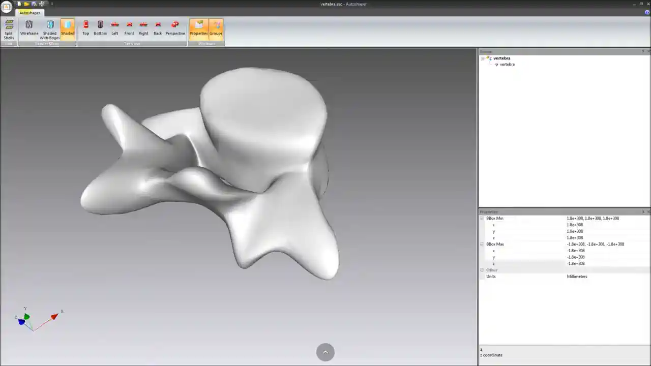
- Open Autoshaper and load your source file via File > Open. Autoshaper will segment the input geometry and fit NURBS patches. Processing time scales with input size and patch density - a 100k-triangle mesh typically completes in under a minute at medium settings.
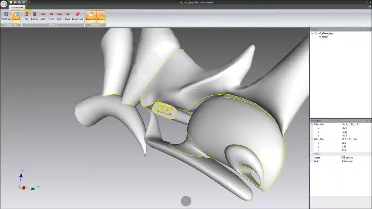
- Review the reconstructed surface in the viewport. Pay attention to high-curvature regions (fillets, transitions between faces) where patch boundaries may introduce visible seams.
- Go to File > Save As and select your target format: STEP for general CAD import, IGES for legacy compatibility, or 3DM for Rhino workflows.
- Import the output file into your CAD tool and verify that the geometry loads as a surface or solid body. In SolidWorks, check the feature tree for "Imported Body" - right-click it and run Check to confirm no errors.
Autoshaper vs Autoconverter - Which Tool to Use
Both tools deal with 3D files but they serve fundamentally different purposes. The choice depends on whether you need NURBS reconstruction or format conversion.
| Task | Autoshaper | Autoconverter |
|---|---|---|
| Convert STL to OBJ, FBX, SKP, GLB | ❌ No | ✅ Yes |
| Convert mesh to STEP as faceted BREP solid | ❌ No | ✅ Yes |
| Reconstruct NURBS surfaces from mesh or point cloud | ✅ Yes | ❌ No |
| Export NURBS to STEP, IGES, 3DM | ✅ Yes | ❌ No |
| Adjust tessellation quality | ❌ No | ✅ Yes |
| Reverse engineer scanned part for CAM machining | ✅ Yes | ❌ No |
| Batch convert large folder of mesh files | ❌ No | ✅ Yes |
| Convert XYZ point cloud to editable CAD geometry | ✅ Yes | ✅ Yes |
If your goal is to change the file format of a mesh without reconstructing it as parametric geometry, use Autoconverter. If your goal is to make the geometry editable in a NURBS CAD tool, use Autoshaper.
Frequently Asked Questions
My reconstructed STEP file imports as a surface body in SolidWorks, not a solid. How do I fix it?
A surface body result means the NURBS patches do not form a fully closed shell - there are gaps between adjacent patches at boundary edges. This typically happens when the source mesh had open boundaries. In SolidWorks, you can also use Insert > Surface > Knit with "Try to form solid" to close small gaps after import.
Can Autoshaper handle very large point clouds - tens of millions of points?
Large point clouds require significant RAM. As a practical guideline, allow approximately 4–8 GB of RAM per 10 million points. For very large datasets, consider decimating the point cloud in a dedicated point cloud processing tool (CloudCompare, for example) before importing into Autoshaper - reducing to 1–2 million points while preserving surface shape is usually sufficient for NURBS reconstruction.
What is the difference between STEP and IGES output from Autoshaper?
Both carry NURBS geometry. STEP (ISO 10303 AP203/AP214) is the modern standard and is preferred for new workflows - it has better support in current CAD tools, supports color and assembly structure, and is actively maintained. IGES (Initial Graphics Exchange Specification) is an older format maintained for backward compatibility with legacy aerospace and defense toolchains that have not migrated to STEP. Use STEP unless your target tool specifically requires IGES.
Is there a free trial of Autoshaper?
Yes. Download the free trial of Autoshaper to test NURBS reconstruction with your own mesh or point cloud files before purchasing.
Summary
Triangle meshes and point clouds cannot be directly edited in parametric CAD tools - they need to be reconstructed as NURBS surfaces first. Autoshaper automates this reconstruction: it reads XYZ, PLY, STL, OBJ, SKP, and 3DM input, segments the geometry into surface regions, fits NURBS patches using least-squares approximation, and exports to STEP, IGES, or Rhino 3DM. The output opens as editable surface or solid geometry in AutoCAD, Rhino, SolidWorks, CATIA, and other professional CAD tools - enabling reverse engineering, CAM machining, FEA simulation, and design modification workflows that are impossible with the raw scan data.
👉 Ready to convert? Download Autoshaper and try it for free.